The antenna is of quadrifilar helical design and constructed from copper wire and PVC pipe. The conductor is 4.1 mm (6 gauge) solid copper wire. The central post is PVC waste pipe with a 56 mm OD. The support rods are 22 mm PVC pipe.
The excellent on-line calculator at http://jcoppens.com/ant/qfh/calc.en.php was used to calculate the antenna dimensions. I also made heavy use of the technical report TECHNOTE 1999-1: Resonant Quadrafilar Helical Antenna”, R.W. Hollander, 1999, to inform the construction technique and to support interpretation of the output from the calculator. One the observations of this report is that narrow conductor diameters decrease the antenna bandwidth, implying that dimensional accuracy is critical to achieve resonance at the design frequency.
The antenna was designed for a centre frequency of 137.5 MHz, a conductor diameter of 4.1 mm, and bending radius of 13 mm. The bending radius was based on the conductor diameter bent around a former of 22 mm PVC tube. This resulted in an antenna approximately 860 mm height, 320 mm diameter.
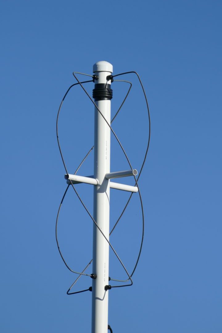
Quadrifilar Antenna for 137.5 MHz
The conductor tends to be quite “springy”, it is therefore clamped as it passes through the central post by M12 cable glands, and by friction fit into slots in the ends of the support rods. Each half loop of conductor was manually shaped using a rubbish bin of the approximate diameter with accuracy of the bends being ensured by a custom-built former. The cable connections at the top of the antenna are based on a variation of that shown in Figure 2 of G0HPO’s site at http://www.askrlc.co.uk/, however due to the smaller conductor diameter I tied the conductor to the PCB using copper wire and then soldered everything for maximum strength. At the bottom each pair of half loops are joined by soldering end-to-end with the join then being slid inside the central post.
The isolating choke balun is 4 turns of the feeder cable to eliminate any RF signal flowing on the outside of the cable, and therefore minimise any impact on the antenna radiation pattern. I used FT125 75 ohm low loss satellite cable and accepted the 0.2 dB mismatch loss relative the nominal antenna impedance for the convenience of ‘F’-type connectors and relatively inexpensive cable.
The antenna is mounted on top of a 4 m length of similar 56 mm OD PVC pipe with three guy wires to ground anchors. Although fairly flexible this setup has so far withstood a few Irish gales.
Unfortunately I don’t have the equipment necessary to characterise the antenna, however if worked first time out and the overall system performance seems good even with a 30 m feeder and no LNA.
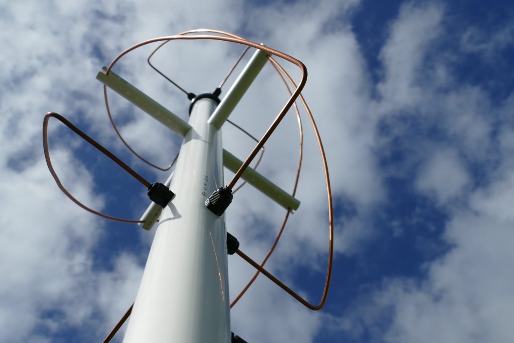
Quadrifilar Antenna from below
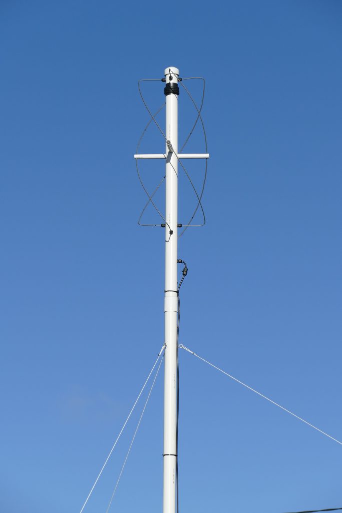
Quadrifilar Antenna mounting
Appendix: Antenna Design Dimensions
For reference the complete antenna design dimensions generated by the John Coppens on-line calculator are presented below.
Antenna Calculator Input
| Design frequency | 137.5 MHz |
| Number of turns (twist) | 0.5 |
| Length of one turn | 1 wavelengths |
| Bending radius | 13 mm |
| Conductor diameter | 4.1 mm |
| Width/height ratio | 0.44 |
Antenna Calculator Results
| Wavelength | lambda= | 2181.8 mm |
| Compensated wavelength | lambda’= | 2330.6 mm |
| Bending correction | c= | 5.5 mm |
| Larger Loop | ||
|---|---|---|
| Total length | L1= | 2391.2 mm |
| Vertical separator | V1= | 886 mm |
| Total compensated length | Lc1= | 2413.5 mm |
| Compensated vertical separation | Vc1= | 860 mm |
| Antenna height | H1= | 728.8 mm |
| Internal diameter | Di1= | 316.6 mm |
| Horizontal separator | D1= | 320.7 mm |
| Compensated horiz. separation | Dc1= | 294.7 mm |
| Smaller Loop | ||
| Total length | L2= | 2272.3 mm |
| Vertical separator | V2= | 842.4 mm |
| Total compensated length | Lc2= | 2294.6 mm |
| Compensated vertical separation | Vc2= | 816.4 mm |
| Antenna height | H2= | 693 mm |
| Internal diameter | Di2= | 300.8 mm |
| Horizontal separator | D2= | 304.9 mm |
| Compensated horiz. separation | Dc2= | 278.9 mm |
freesam September 15, 2023
Hello. What is the length of wire needed to bend the loop. Which parameter is this from the calculator?
admin September 24, 2023 — Post Author
Hello. The total length for each loop is the “Total compensated length (Lc)”.
sam November 22, 2023
Dear Sir,
I would like to do some weather reception tests with my RTL-SDR.
Would it be possible to build one for me and I’ll pay u for the antenna ? i do not think I’ve the skills to build one. Ideally, with male SMA connector. I live in France and really like the job
you’ve done.
Thanks in advance.
Best regards
admin November 25, 2023 — Post Author
Hello. Thanks for your interest in the antenna. Unfortunately at this time I’m not constructing any to order as they are fairly complex to assemble and tune. As an alternative I would suggest the design below if you are looking to get started. It works well, and is very simple to construct. For optimum results place it about 1 m above the ground or add a reflector. Good luck!
https://www.rtl-sdr.com/simple-noaameteor-weather-satellite-antenna-137-mhz-v-dipole/