The receiver consists of two parts: the SDR receiver hardware based on an RTL-SDR USB module, and the SDR tuner and demodulator software running on a Raspberry Pi.
Receiver Hardware
The receiver hardware is an RTL-SDR Software Defined Radio module using the RTL2832 + R820T2 chipset. This can be found at NooElec NESDR Mini 2+ 0.5PPM TCXO USB RTL-SDR Receiver. The RTL-SDR module is connected to a Raspberry Pi 3 Model B which hosts the demodulator and image generation software.
The RTL-SDR was modified by replacing the 50 ohm MCX connector with a 75 ohm ‘F’-type connector. The RF input to the R820T2 is 75 ohm, so this eliminates a potential impedance mismatch and allowed the use of cost effective ‘F’-type connectors and low loss FT125 satellite cable. This combination is also more convenient for home use without specialised tooling.
Initial experiments with the RTL-SDR connected to a PC showed heavy interference in the 137 MHz band from USB 2.0 data and my HDMI-connected LCD monitors. As a result I placed the RTL-SDR remotely using a USB extension cable. I also removed the RTL-SDR USB connector and instead directly wired a USB cable, leaving the shield disconnected to eliminate a potential ground loop. I also added ferrite EMI suppressors at the computer end of the cable to reduce conducted emissions. There is further discussion of similar approaches here and here.
Currently the RTL-SDR is located at the end of about 30 m of FT125 feeder from the antenna, incurring some 1.5 dB of loss, however the eventual plan is to locate it and the Raspberry Pi at the base of the antenna mast. The RTL-SDR is configured for maximum RF gain (~50 dB), making it somewhat desirable to add an LNA to improve the overall system RF noise figure in a future upgrade.
The Raspberry Pi is using stock Raspbian software and uses Wifi to connect to my home network and from there to the internet. An external 4 GB USB memory stick provides backup storage for about 30 days of imagery.
Good timing accuracy is important for correctly aligning the received signal with the map overlays. Instead of ntp I am using chrony, to help compensate for the lack of a stable real-time clock (RTC) on the RPi and intermittent network availability. Typically this achieves a reported alignment with UTC to much better than 1 ms (usually about 300 us).
NOAA APT Signal Demodulation
The NOAA APT signal generation AM modulates a 2400 Hz subcarrier with the luminance channel, and then uses the resulting modulated tone to FM modulate the ~137 MHz RF carrier. From the NOAA User’s Guide for Building and Operating Environmental Satellite Receiving Stations the maximum FM carrier deviation (i.e. peak white) is +/-17 kHz. By using FM modulation the APT signal is essentially immune to satellite Doppler shift (which can peak at +/-4.5 kHz for an overhead pass), provided the receiver IF bandwidth is sufficient. The ideal receiver IF bandwidth is therefore in excess of 43 kHz.
The receiver demodulator was implemented in Lua using the LuaJIT compiler and the LuaRadio library. The baseband sampling is configured for an IF 40 kHz bandwidth at 1.102500 MS/s, simplifying decimation to a final audio sample rate of 11.025 kS/s. Offset tuning of 250 kHz is used to avoid the signal image contaminating the wanted signal. An FM discriminator is subsequently used to extract the subcarrier. The FM modulation index parameter of 1.0 essentially controls the amplitude of the demodulated AM signal, and was chosen arbitrarily (lower values give higher gain). A lowpass filter with a cut-off at 5.5 kHz is used to minimise excess audio noise while preserving the AM modulated 2400 Hz luminance carrier. Although the IF bandwidth is less than ideal this was found to be reasonable trade between excess noise/interference and received signal power, while also avoiding some significant discrete interfering carriers that were observed in-band.
-- Example usage: luaradio rtlsdr_noaa_apt.lua 137.62e6 recording.wav

local radio = require('radio')

if #arg < 2 then
    io.stderr:write("Usage: " .. arg[0] .. " <RF centre frequency> <Output filename>\n")
    os.exit(1)
end

local frequency = tonumber(arg[1])
local output_file = tostring(arg[2])
local tune_offset = -250e3
local if_bandwidth = 40e3
local af_bandwidth = 5.5e3

-- Blocks
local source = radio.RtlSdrSource(frequency + tune_offset, 1102500, {rf_gain = 50})
local tuner = radio.TunerBlock(tune_offset, if_bandwidth, 10)
local fm_demod = radio.FrequencyDiscriminatorBlock(1.00)
local af_filter = radio.LowpassFilterBlock(128, af_bandwidth)
local af_downsampler = radio.DownsamplerBlock(10)  -- Need 11025 as output rate
local wav_sink = radio.WAVFileSink(output_file,1,16)  -- Single channel, 16 bit samples

-- Connections
local top = radio.CompositeBlock()
top:connect(source, tuner, fm_demod, af_filter, af_downsampler, wav_sink)

-- Let's go
io.stderr:write("Recording from " .. frequency / 1e6 .. " MHz to " .. output_file .. "\n")
top:run()
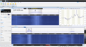
The screenshot below shows the various signals in an equivalent demodulator using the SDRConsole V2 software on a Windows PC.

Lower waterfall shows two NOAA satellites in view at 137.62 MHz (NOAA-15) and 137.9125 MHz (NOAA-18), upper waterfall shows FM-modulated IF signal with ~40 kHz bandwidth with some Doppler shift apparent, audio spectra on right shows 2400 Hz AM modulated luminance subcarrier.
The demodulator writes the resulting AM modulated 2400 Hz luminance subcarrier as an audio signal to a single channel (mono) WAV-format file at 11.025 kS/S, this sample rate being a requirement for the subsequent image generation software. A sample from one of the resulting WAV files can found below.
Control of the receiver to capture the signals from satellite passes is described in Receiver Control.